Modeling Confusion!?!? Please Help SOLVED!
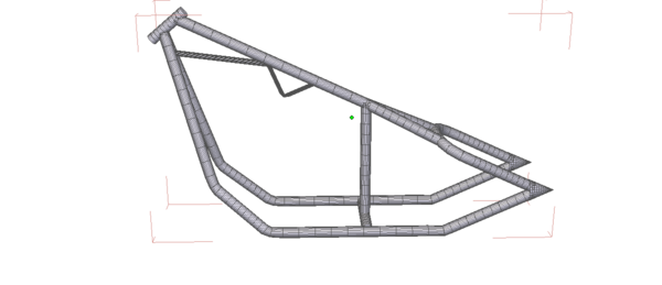
Hi All, Not quite sure this is the right place for this thread, Anway I am trying to model a custom chopper in hexagon and I am having an issue with the frame and wondered if there were some tips or tricks that someone can point me to. I have created the frame in the picture from a Total of 19 cylinders and positioned them and welded them together. I am certain I am going to have difficulty UV mapping this frame to apply a decent texture to it. so my question is this; Have I done this the best way possible and if not how could I do it better to get it to UV map properly.?
Thanks for reading and for your time. :)
Edit Marked Solved


Frame.png
1244 x 536 - 94K
Post edited by mrbpjohnson on


Comments
What are you modeling it to be used in?
The reason I ask, is that unless you are wanting something like flames or other artwork, then the UV mapping doesn't have to be 'spectacular' for using a paint/metal procedural or shader based material.
Hi, I am modeling this to be either a chrome freame or a powder coat finish , But when I apply my chrome texture it is really bad, seams and overlaps and such. I understand that most of the frame is going to be hidden once the rest of the model is applied but the parts that are exposed will need to look sharp. I try to keep my renders as close to reality as possible unless Im doing a fantasy render.
Edit added picture
UV mapping with complex shapes can always be a tricky endeavor even when you're quite experienced. The one thing to remember is that you can use multiple mappings for different parts of the frame. This will help you get your seams in the right places and give you greater control when arranging the polys onto a template.
Sadly I can't help much with specifics since I don't use Hexagon for UV mapping (I use 3D Studio Max) but the procedures are fairly similar for most modeling applications.
@ HeraldOfFire Thank you for the input, so would it be best for me to UV map the cylinders before I weld them?
Not necessarily. It's almost always better to work on a finished model, because the simple act of welding pieces together would not create seams, and would in fact cause texture distortion around the weld. As I've said though, most modeling applications allow you to perform multiple mappings onto the same object for different polygon selections. In 3DS Max this is done by selecting the affected area and then setting the type of mapping you want to use for that section. Max automatically creates the seams at the edges of your selection, allowing you to separate those pieces on the final template.
An example is below, again this is 3DS Max. The green lines show how I've used different types of mappings to split the model into individual panels for easier texturing.
I see, Basically I just need to be careful of where and how many seems I add, and the more seems i create the better the texture would look when applied, I think I get it.. still trying to figure all this out have only been doing this for about a month and a half so... still a long way to go
That actually worked quite nicely I think, Thank you for the tips and the help :)