hexagon made door issue
 aliendoughnut
Posts: 40
aliendoughnut
Posts: 40
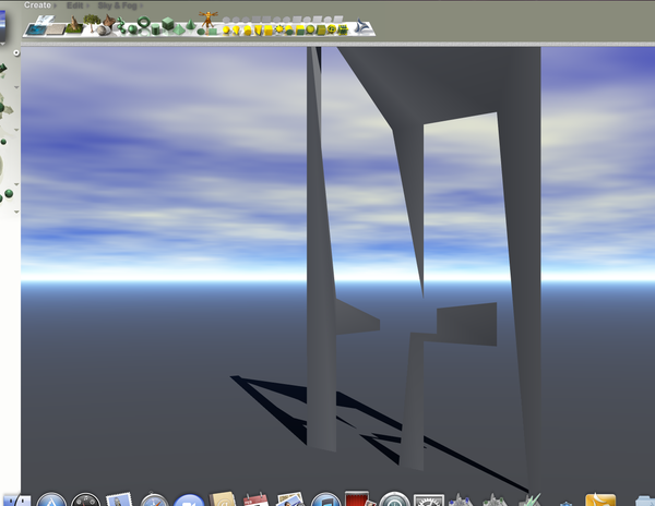
hope someone can help i am modelling a simple door and i am having issues when cutting a hole for the letterbox the following 3 pictures will show what my problem is.after cutting a hole in the door the geometry seems to be badly effected which is visible when i import the object int bryce.
first picture before i cut the hole
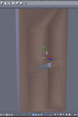
second picture after i cut the hole
third picture is the results in bryce
Screen_shot_2014-02-05_at_19.34_.47_.png
1260 x 975 - 331K
Screen_Shot_2014-02-05_at_19.40_.57_.png
631 x 954 - 166K

Screen_Shot_2014-02-05_at_19.40_.01_.png
802 x 939 - 99K
Daz 3D is part of 
Connect
DAZ Productions, Inc.
7533 S Center View Ct #4664
West Jordan, UT 84084
Licensing Agreement | Terms of Service | Privacy Policy | EULA
© 2025 Daz Productions Inc. All Rights Reserved.
Comments
I don't use Hex so not sure about your fix. In my app I'd have to add in more poly around the hole to reinforce the shape. Are you beveling your edges?
why bolean the hole? its a simple rectangle, cut out the mesh for the hole
What dot.bat writes is correct - but there is a lot more to it than that - the geometry of the whole door is all wrong, with n-gons all over. I'm surprised Hex managed to export the .obj without crashing.
Trying to figure out how you managed to make the inset panels without edges connecting to the outside edges - unless you dissolved them after making the panels?
Hi The pic doesnt show all the lines! i used teselation by slice to mark up the door where the door panels are located with a pic of the door behind to get the lines in the correct position, i then selected one of the panels using the face selection and used the line tool to extract a line inwards to create the inside edge of the panel then selected the face and moved it inwards to create the final effect. i deliberatly didnt remove any edges incase this was causing the issue
Roygee
I know the tips you posted in another thread about Hex crashing has been my salvation and I now use Hex quite a bit. It still has stability issues but just not quite as frequently.... Using Hex is now not only manageable but very enjoyable...
Many thanks for your tips...
If you have the wires something like this you should be ok in bryce.
mine looks like this without the letterbox cut out am i doing something wrong?
Looks ok to me. Only thing is the boolean. Stay away from it if you can when modeling in Hex.
Bryce is really good with Booleans so you might wanna do the hole in bryce instead.
yes all my previous modelling has been done in bryce i just need to think differently in hex.....
Thanks for all the help!!!
Hi aliendoughnut :)
My apologies - thought your pic was the wireframe.
Your model without the letterbox looks really good.
Something you may want to try for making the hole is what I refer to as "fake boolean". Cut in the edges you need for the hole - make sure they loop all the way round the model - select the front and back faces of the letterbox hole and bridge them. Makes a really neat hole without the hassle of boolean.
to me the easiest way would be to use lines and the first option in edge tools under vertex modeling tab.
with a flat rectangle as the base, I'd select the top and bottom horizontal lines, and using edge tool to extract along and create some new lines. then I'd do the same with the left and right vertical lines, etc. Then finally once I had my 4 rectangular boxes in the center, I'd select all the rectangles lines and reinforce it with a thin extract along (i.e. a box within a box) THEN I'd select the face and do an extrude surface (or two, again, to reinforce the lines).
This is the easiest and most efficient way of doing it, especially when it comes to limiting the amount of vertices/faces for rendering performance, and to ensure your geometry doesn't get messed up in case you need to manipulate it, since the extrude doesn't depend on the outer lines for reinforcement.
Ending up with something like the attached photo I've included.
I've also included an alternative door with a different line structure to show there's more than one way to do it and that not necessarily everything needs to be reinforced through dividing them up into smaller sections.
Get used to using lines and edge tools, it may be more work than boolean but it is a heck of a lot more stable and allows you to perfectly align things easily. You can typically do these things as fast as you would using boolean. You can also use these lines to create grooves between sections to give the appearance of an assembled object and a more robust detailed model.
Some usefull tips....thanks