Can someone help me understand proper use of displacement?
 cheard
Posts: 87
cheard
Posts: 87
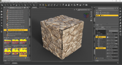
Hello, friends! The attached image shows a cube primitive (0.5 m) with a shader applied (specific shader highlighted in the image). Of course just applying the shader to the primitive produces a rather "flat" look, but if I turn up the displacement enough to get the surface to look great, the edges of the cube peel away from each other (due to displacement working as expected, I infer) and therefore the shape as a whole is unusable although each face is really good for my use case.
I feel that I must be doing something wrong here, but I am not savvy enough to know what it is.
In the actual scene that I'm working on, I have multiple such "cubes," resized into rectangles of varying heights and widths, with multiple surfaces defined using the geometry editor to help with the tiling. But the edge problem occurs consistently whenever I turn up the displacement.
Grateful for any guidance!
Chris
Daz 3D is part of 
Connect
DAZ Productions, Inc.
7533 S Center View Ct #4664
West Jordan, UT 84084
Licensing Agreement | Terms of Service | Privacy Policy | EULA
© 2025 Daz Productions Inc. All Rights Reserved.
Comments
Here's an additional note. I played with the rounded cube from SY's Morphing Primitives, applied the same shader and settings, and when it is cubic (h = w = d) everything looks nice. But if I scale one dimension alone, then alter the tiling, the look is inconsistent around the primitive because "vertical" and "horizontal" don't mean the same thing on all faces of the primitive. Also, rounded corners won't really work for my use case, since I am stacking the blocks/rectangles together to make walls of various dimensions.
Additionally, I tried leaving the displacement off, making a geoshell, and applying the same shader with displacement to the geoshell. But that did not work well; you can see the original cube through the cracks in the geoshell, but there's enough distance that it looks odd.
I have also tried setting the minimum displacement lower and the max displacement to zero, but that produces an "inset" effect that isn't appropriate to my use case.
1stly, add more division when creating the cube. 2ndly, convert the cube to SubD since you add displacement with SubD onto its surface...
Returning to this topic after a hiatus to focus on other projects. When I convert to SubD as incidated by crosswind, my cubes end up with curved edges, but I need the edges "sharp" to stack them together into walls. What can I do about that?
Are you also increasing the mesh resolution on the primitive when it's created? Adding subD to a low-resolution cube will round the edges, but the effect will be much less pronounced if the thing you're applying subD to has more divisions.
Yes, I am ... but since I am not super savvy about this, perhaps I need to go higher? Is there a "rule of thumb" for how many divisions to use?
In Iray, displacement only works on vertices, either "real" ones created when you create the object mesh, or subD vertices created with subdivision. The amount of resolution you need will depend on the displacement map used, and the strength of the displacement applied in the Surfaces pane, and the min and max displacement values applied in the Surfaces pane. If you make your mesh too dense with high subdivision values, Daz Studio will declare it to be too dense and adjust your selected subdivision value down. That adjustment will be shown in the Daz Studio log. There is no pop up message to inform you.
Yes ~~ and for OP's case, 60 ~ 80 divisions should do. But such a "ultra displacement" settings on a primitive Cube may always bring you that issue on the edges... so better use a normal settings on such a cube or use ultra settings on a pure surface.
One possible cause not mentioned so far is that smoothing of the edges may be coming from the shader.
The Iray DAZ Uber shader is designed to smooth across facet boundaries and has an 'Angle' setting below which the facet boundaries are smoothed. The default setting is 89.90 degrees, but it may be worth reducing this quite a lot or turn off the 'Smooth' switch in the shader. Also where it says 'Smooth across material boundaries', switch that off. This may not be the cause here, but it's one possibility to bear in mind when these effects appear.
A way of guaranteeing that the edges do not smooth is to create the cube from 6 independant faces that don't share vertices. This normally requires the model to be made outside DS as it's a right pain to manipulate faces in DS.
Regards,
Richard
Unfortunately they didn't help. Though the texture maps were made to be seamless, that cracked issue just happens to the "non-seameless edges" with the disp map on the cube, and there're only 3 seamless edges among 12 ~
I'm still testing in other ways with such a "ultra displacement settings" ~