Weird UV Maps, Mystery Surfaces
 CrissieB
Posts: 195
Well, um.
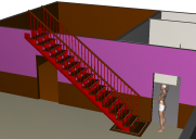
The first pic is a render of a Basement set that I'm modeling in Hexagon, with a G3F there for scale.
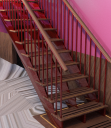
The second pic is an incomplete render after I sent it to DAZ Studio. Where to begin....
For starters, my UV maps are apparently a mess. I made the floor as a plane, gave it a plane UV map, divided it into four shading domains (one for each room), and assigned each a color-only material. I planned to apply Iray textures in DAZ Studio. But somehow the UV map turned into a swirly mess. The same is true for all of the walls, and most every other object.
Then there's the mystery surface on my stairway struts. To make the struts, I began by drawing a facet for the profile, starting in the bottom right, with 16 up-and-then-left segments, a downward segment at the left edge, a diagonal segment along the bottom, and a rightward segment to complete the facet. Then I repositioned each point according to my rise-run calculations, with 20cm rise and 27cm run for each tread. Once I had the profile shape correct, I gave it 5cm thickness, chamfered the touchable edges, applied the plane UV map, and assigned it a color-only material. I then copy-pasted two more struts, positioned them, and welded them into a single object. Somewhere in that process, Hexagon added a mystery diagonal surface along the left face of each strut. I have no idea where it is or how to remove it....
Do I need to custom UV-map each object? Would that process reveal the mystery surface on my stairway struts, and could I remove it then ... or will I have to go back and make it again and hope I don't repeat whatever mistake I made this time?
Thank you for your help. :-)
Crissie


Comments
Oh, also, when I sent this to DAZ, most of the surfaces (floors, walls, etc.) came in with the Diffuse Color set to some part of the Jeanne figure. I have no idea why.
Can you do me a favour, it would be easier to see what is going on if you render it with 3Delight rather than Iray. (3Delight, if you set the material to white any normals facing the wrong way will show up as black).
Also, export the set (without the character) as an obj file.
About the steps, when you weld objects together you loose the UV map, sorry but I think you have to do them again.
The floor, this looks like you have lost the map.
For the first pic I selected all of the objects in Hexagon, sent them to DAZ via the Hexagon bridge and rendered in 3Delight. For the second pic, I selected all of the objects in Hexagon, exported them as an obj, imported the in DAZ, and again rendered in 3Delight.
As a practical matter, the problem with the second method is that the entire set comes in as a single object. I need the floor, walls, and ceiling to be separate objects, so users can hide them if necessary to get better camera angles. But I could solve that by exporting each object from Hexagon, one by one.
Regardless, the first pic shows that my UV maps are rubbish. Is there any way to delete an object's UV map, so I can UV map it again? Or do I need to delete the object and build it again?
If I followed your description of how you modeled the stairway struts (called "stringers" in construction terminology), you ended up with two huge n-gons on each one (an n-gon is a polygon with more than 4 edges). N-gons are usually not desirable, and can lead to odd looking artifacts.
I would suggest that you model the stringer tessellated (as shown in the attached image) to eliminate the n-gons.
Thank you for the reply. Umm ... *blush* ... what is the most efficient way to model the stringer tessellated, as your image shows? In case it's not already glaringly obvious, I'm a Hexagon newbie. Once I get that basic shape, should I chamfer the touchable edges *before* I UV-map and set the material?
Also, thank you (sincerely!) for telling me the correct construction term. I thought the stringers were the little poles that support the handrail. I just Googled {Stairway construction terms} and learned those little poles are called balusters. I'll correct the names in my scene list.
Okay, I'm trying to replicate what you did, de3an. I began with the grid primitive, 16x16, with a 27cm horizontal interval and 20cm vertical interval. Then I deleted the faces that won't be there. Now I need to connect those bottom points, so there are triangular faces along the bottom. Then thickness, chamfer, UV map, and set materials.
Is this the right way to go about it? And how do I connect those points? I've tried the Bridge, Connect, and Close tools ... and none of them seems to have any effect.
That's a fine way to do it.
Then use the Surface Tessellation tool to snap an edge between the two desired points. The corners can then be deleted.
Use the Thickness tool to finish it off.
Thank you again, de3an. Alas, it seems that sometimes the Surface Tessellation tool goes exactly to the point at the corner, and sometimes it doesn't. (I had Point selection mode on when I tessellated.) I didn't know this until I had the stairway in DAZ Studio.
Before that, though, I ran into another problem. After I added thickness and chamfered the edges, I UV mapped the stringer. But Hexagon crashed when I tried to select unassigned faces to assign a material. It also crashed any time I tried to select any face of the stringer. I finally gave up and assigned a material to the entire object. Then I copied and pasted to place the center and right stringers. I didn't weld them this time, because I knew that would bollux the UV map. Instead I copied and pasted all of the stairway objects -- stringers, treads, balusters, baluster caps, handrail, and landing -- into a new Hexagon file. I exported that file in obj format, then imported it in DAZ Studio.
And that's when I discovered that tessellation hadn't always gone exactly to the point at the corner. Where it hadn't, there were sharp points along the otherwise rounded bottom surface. So ...
... how can I make sure Surface Tessellation goes exactly to the points at the corners?
Pressing the Shift Key will cause the tessellation tool to snap to the nearest vertex.
Chamfering a shape such as this will most likely produce more unwanted n-gons. (At least I haven't figured out how to avoid them.)
They would need to be fixed with more manual tessellation. And fixing one n-gon can often produce another in an adjacent polygon.
Nobody said 3D modeling was easy
Thank you for the tip on holding the Shift key to snap to vertices, and for the warning that chamfering that shape will leave me with n-gons!
That forced me to think of another way to eliminate sharp touchable edges, and ultimately got me back to the design I originally wanted but couldn't find a way to do. Here's what I did:
1. Created a 16x16 grid primitive with 27x20cm intervals, selected the faces that would form the stringer side, inverted the selection, and deleted the extra faces.
2. Used Surface Tessellate, holding the Shift key to snap to vertices, diagonally divided the bottom faces, then deleted the bottom triangles. That gave me the 2D profile for the stringer.
3. Added 3cm of thickness to create a 3D form for the stringer.
4. Shift-selected the edge faces all the way around, then used Extract. I now had two forms: (a) the left and right faces; and (b) the edge.
5. Selected the edge form and widened it to 5cm, so it overlapped the left and right faces by 1cm each.
6. Selected the edge form and added 1cm (interior) Thickness. I now had the I-beam shape that I originally wanted.
7. Loop-selected the inner and outer lines of the edge and chamfered (2mm radius, 3 range) to soften the edges.
8. Shift-selected the edge and face forms and welded them back together.
I zoomed in as close as I could in Hexagon, to look for n-gons and other oddities. (A screen shot is attached.) I couldn't find any, so I sent it to DAZ Studio and zoomed in as close as I could to examine it there. Everything looked fine, so I applied the Iray Cranberry Car Paint shader, added a Distant light source, and rendered. This is on a blank scene; the odd black shape at the bottom right is a shadow cast by the stringer.
Success!
EDIT: For the final version, I'll fit the faces to the interior of the edge form before I weld the face and edge forms back together.
Looks like you're getting a handle on things.
If you haven't already discovered it, there's a Hexagon manual in the Hexagon Docs directory.
You can also find it on-line along with other tutorial info here:
http://docs.daz3d.com/doku.php/public/software/hexagon/2/userguide/start
I think you want to redo the uvmap for the walls, those coloured squares in the you have in the first screen grab are meant to be, well, square (sorry).
I've made a quick wall for you to have a look at, feel free to use and adapt as you wish - Please let me know if this link works -
https://onedrive.live.com/redir?resid=81F9CD7A4CE4C2C!1564&authkey=!AGzr531V0T2UhIY&ithint=file,zip
Thank you, John. The link worked, but I'd already figured out the problem with my UV maps. It turns out that Hexagon creates a default material (e.g.: material29) when I select a UV map projection for an object. I'm using shading domains to apply different textures on each wall and the UV map is part of the wall's geometry, so I thought I could delete that default material. But that default material seems to remember how the shading domains fit together, and deleting it makes the UV map go awry. So when I went back and rebuilt the basement, I renamed and kept those default materials (e.g.: NorthExtWallUV).
I used the six-face cubic UV map projection for the walls, so I could see all of their surfaces unfolded on the map. I then resized each surface to scale. E.g.: the NorthExtWall measures 15x3x0.2m and the cubic projection gave me a 15x15 grid, so I made the front and back surfaces 15 squares wide by 3 squares high. I made the top and bottom edges 15 squares wide by a little under 1/2 square high and the left and right end edges 1 square high by a little under 1/2 square wide. I know that makes the edges too wide, but 1/5 square was too tiny for me to see clearly and work with easily.
I next selected faces on the front side of the wall and created shading domains (e.g.: NorthMainTop, NorthMainBottom, NorthUtility, NorthLavatory). For each domain I created a color-coded material: MainWallTop (pink), MainWallBottom (brown), UtilityWall and LavatoryWall (both off-white). I chose those material names so I could set the same materials to corresponding domains of other walls. Then I selected the unassigned faces (back, bottom, top, and ends) and created a NorthWallUnseen domain, and set an Unseen material (gray).
I then selected the wall and sent it to DAZ Studio, where I created custom shaders for each material. I worked from DS 4.9's built-in Iray shader presets, swapping in my custom texture and bump images and/or colors. I saved my custom shaders as presets, again so I could apply them to corresponding parts of other walls.
Attached are a Hexagon render of the 'raw' Basement floor and walls, and DAZ Iray renders of the floor and north and south exterior walls. I textured the Main (east) room floor with beige carpet and the Main room walls with dusty rose satin wallpaper over dark wood panel wainscoting. I textured the Second (southwest) room floor with light wood floorboards and its walls with the dark wood panel. I've textured the Utility Room (north center) and Lavatory (northwest) floors with ceramic tile and the walls with off-white paint on textured wallboard.
I'm using shading domains and materials in Hexagon, with corresponding shader presets in DAZ Studio, so other users can create their own shaders to change the look of the set. I hope to sell the set at DAZ, and I plan to create shader presets for three setups: (a) home basement with rec room (Main), computer/craft room (Second), and laundry room (Utility); (b) private casino club with bar/cardroom (Main), sauna (Second), and coatroom (Utility); and, (c) apartment/condo fitness center with a large workout room (Main), jazzercise room (Second), and cubby-lockers (Utility). For the private casino club setup, I made an alternate Main-Second wall with no doorway.
In all three setups, the Lavatory will have a commode, basin sink, and shower. I'll model and include some other props including a stairway, light fixtures, baseboards, chair rails, cornices, heating vents, light switches, thermostats, and wall outlets. But I don't plan to model common props that users can download for free from DAZ or other content-sharing sites.
Glad you sorted it. Personally, I do not like using the "Projections" UV modes, I prefer to unfold things by hand. I like the textures you've created for the walls, good luck with this project :)
Thank you, John!
I'm not yet skilled enough to unfold UV maps by hand, and from what I've read Hexagon really isn't the best software for creating complex UV maps. But a wall is basically a cuboid, so Hexagon's cubic projection works well for what I need.
Attached is a screen shot of the EastExtWall UV map. (I added a rectangle and shading domain labels to the screens shot.) This is not how Hexagon unfolded the wall by default, but that's how it looks after I resized and moved the surfaces. The rectangle encloses the surfaces in the Unseen domain: the back with the top and bottom surfaces immediately above and below it, and the end surfaces below those. At the bottom is the front surface of the wall, with the EastMainTop and EastMainBottom domains. This wall is 10x3x0.2m and the grid is 10x10, so I made the back and front surfaces 10x3, the top and bottom 10 x about 1/4, and the ends 3 x about 1/4.
Also attached is a DAZ Studio render of the east wall, with my Iray shader presets applied.