Adding to Cart…

Licensing Agreement | Terms of Service | Privacy Policy | EULA
© 2025 Daz Productions Inc. All Rights Reserved.You currently have no notifications.

Licensing Agreement | Terms of Service | Privacy Policy | EULA
© 2025 Daz Productions Inc. All Rights Reserved.
Comments
ok, I have a few thoughts about the top of the SilverStone PM01, and I will start it all off by saying this case has more airflow space between the covers and metal than most other cases I've seen the past seventeen years. Otherwise, I would just outright delete the top and start from scratch. That does not imply that the case does not have room for improvement. The hight of the top above the rad is sufficient, however, the exhaust and duct width is a bit limiting for two 120mm fans.
Add to that the choice of stamped speaker grill and how restrictive it is for airflow. I do understand why the speaker grill was chosen, it's a very good choice for the front in that it is strong and resists denting and flexing far better than other screen materials. so simply adding another screen type to the parts list would cost more and add more to the manufacturing process. My dilemma is that it is restricting an already too small exhaust vent for the top rad. Time to open it up and play with some mods.
the top also has a few things that could be smoothed over for better airflow, especially as the rad fans are blowing air up at the lid. The flat walls cant be removed without making the top flimsy, however, the steep face of them can be made more fluidic for airflow.
So after all that, I still have mixed feelings about the exhaust vent.
even with that massive wall at the top remove, it's still way too small for two 120mm fans.
The mods so far have massively improved airflow, and I think it can be much better.
I could take the time to file the underside of the exhaust triangles into something resembling a vane or blade, however, I feel that will not provide enough.
The end of the day there is 20k mm^2 of air trying to get through less than 6k mm^2 of opening, that is not going to work well.
Something to keep in mind, before you start modding your comp. Once you mar up the surface of plastic or metal, it Will NEVER have that pristine new look to the surface Ever Again. Keep it stock and be happy with what you got, or except that modding will take away "the new look" for whatever goal you have for your mod (and things can break in the process).
ok, a little bit of an update on Senior Ice. I had been jokingly asked why don't just remove the top rather than fuss with the back vent.
well, I'm at a point that I need to test some stuff anyway to see if other stuff has any chance of improving temps at all. And so the top was already off for measurements and pondering of over many cups of coffee. so it was just a mate of figuring out what pigtail had the power button to fire the beast up for a no exhaust restriction test of the rad anyway.
Well, with some preliminary numbers in, it looks like the temps are only 2c better with no top at all than the modified grill with no screen in it yet. That's not much at all, and not that encuriging. I was really hoping to get the water temps down a lot more than just 2c, tho I guess I'll need to move the rad over to try other fans to see if it has a chance of getting any cooler.
The temps are not bad at all, I was just hoping to make them a bit beter. As for moving the rad and getting the air to the back eficantly, I will need to look at that and ponder it over many more cups of coffee, lol.
I know I've been quiet the past few days, been wrestling with stubborn dives and windows update having difficulty updating one of the problematic drivers.
The two different USB controllers were squabbling like siblings over DMA and IRQ sttuff, and some other things as well.
Tho after blind end user mashing buttons for a week, that win update finally installed. the comp was willing to run for the past 24 hours without spontaneously cashing.
So, I may finally have this thing ready to really look at thermal improvements, because running a fan full tilt to keep the VRM blocks cool is just not cool for a daily driver system.
so, for running at stock clocks, is not too bad. overall the responsiveness so far appears to be better than the FX, tho I have not attempted o stat multitasking on the system yet.
3delight rendering is not too bad, as long as you limit the AoA subsurface shaders in use, at stock R7 1700 (non-x) clocks.
So eventual I hope to do some render tests, tho cooling the VRMs is still a major concern.
ok, I looked at some stuff, and drafted up an idea. Now I did say that the Gigabyte Gaming 5 motherboard had heatsinks instead of thermal mass blocks. The prob is the cooling fins are down under the heatsink where there just not going to get cool airflow over them, lol.
so I ordered few copper bars to trim up and bolt on actual heatsinks too.
and that should place the cooling fins where there is airflow to cool the thing.
Now, I do not have all the measurements just yet, I still need to remove the stock heatsink to get the calipers in there to measure the rest.
it looks like if the MST-88 was 100mm hole spacing instead of 88mm spacing it would drop in, however, I'm not sure of the hole offset or bar width completely yet. I'm also not sure the MST things are tall enough for the pins to get into the airflow at the back of the computer.
I've been asked a few times about just cutting more fins into the stock VRM heatsinks, and there is a lot more to it than just blindly making more groves in a lump of mettle.
First I would like to remind others that there is another side to heat-sinks than just lots of surface area of a good metal. Heat needs to flow from the heat source to the furthest fins, the longer and/or thinner that path, the less heat will make it to the furthest fins. Think of it like the heat flow being a river and the metal is the channel the river flows through. the deeper and wider the channel, the more heat can move through that channel.
When you cut a fin into a block, you also reduce the amount of metal that can curry heat to the fins. And with long thin heat-sinks like the 100+ mm long thing on motherboard VRMs, removal of metal can drastically weaken the strength and ruggedness of the heat-sink that needs to mount flat onto 'All Of' the fets.
So even making a few select cuts, can adversely affect how much heat is making it to the fins at best, and cause the heatsink to bow and not cool the centermost fets in the wost of cases. That is the other reasons why I did not immediately rip off the x370 gaming 5 VRM thermal blocks and cut as many groves in them that my blade width would let me, and that is only the beginning down this road and does not even consider deburring the cuts and backups if something breaks.
Taking a Dremel hacksaw and file to your motherboard is NOT covered by any warranty, and neither is the GPU if metal shavings fall off the VRM blocks and short out that. You really need to know exactly where you're at and where you're going to go before you start cutting anyything.
ok, I know I haven't posted anything in a few days, been running test after tests after tests.
So, as for the former thing I was asked I found the results to be similar to what GN found out about the VRM thermal blanket (IO cover), the heatsink is so anemic that cutting fins in it did not add much at all for surface area, resulting in about 2c improvement, at best. So, I don't think that was worth wrecking the look of the stock block for. it just was not worth the effort, to be honest.
Today, some stuff arrived, and I'll start measuring the parts and trimming up the base for the replacement heatsink soon I hope.
Tho I think I underestimated just how long the copper bars are when placing the order.
Also, I replaced the stock black oily rubber thing with that blue thermal pad, and that also gave a 2c improvement in temps.
That's a lot of only 2c results so far, I think it's time to ditch that stock thing and go with something that can actually dissipate over 12 watts of heat, lol.
A little bit of a wee hour of the morning update.
I had initially planned to cut up one bar of each width, and use the one that fits best on the VRM FETs, with the leftover one as a brace on the back of the board with a thermal pad under both bars.
The bolts I have tho are a bit short for that, and the copper base very heavy. I think I may just use some Aluminum 'U' channel on the back instead. It is looking like the thinner bar may be just a tad too thin to do what I had in mind, however, the wider bar is going to be a lot more cutting to get around stuff.
ok, just before I headed outside to work on metal without getting metal dust and shavings in here, I decided to look at how the mount holes line up with the placement of the fets.
All the fets being on the one side of that white line and nothing on the other to keep the heatsink from rocking off the fets, just about solidified what direction I had to go. I'm going to have to use the wide bar and them chips in the green area to keep the heatsink base flat on the fets.
I had thought about putting the heatsinks on the bar at an angle to sort of make a diamond staggard pin-fin array. I had to borrow my neighbor's drill and didn't want to fuss with cleaning up the shavings to fit test every cut, I just wanted it done, lol.
Well, I have a lot of cleaning up to do, and some more boxes arrive I need to inventory, so, much too be doing's
ok, a short pic collection of what is up and running and undergoing thermal tests now.
I was going to put the MX4 between the copper bar and heatsink, or that was the initial plan.
Tho someone asked if I was just going to go with two thermal pads (guess the one that came with the AAVID heatsinks), and that had me thinking "How bad can that be if you have a real heatsink" so I gave that a shot. the first test being with the 6W/mK blue pad on the fets and the white sticky stuff the AAVID heatsinks came with. I may not swap that AAVID white tape out for MX4 if it's good enough as is, lol.
So far it is looking very good.
(R7-1700 non-x, at stock clocks and voltages) I think That will do back to normal OC.
morning. A little bit of a rambling as to why I'm even doing all of this. It's for a few reasons that I guess many do not totally grasp the impact of, considering how many jump in mi conversation only to ask why or just shun outright without considering where I'm coming from. First and foremost is that I am not rich so what I have needs to last. Simply replacing subpar components yearly is just not in my budget. And I need this stuff to work without question with a level of reliability that most cannot grasp. It's one thing if the computer crashes in the middle of a game and your out an hour tops of beating a level, it's entirely different when the comp crashes day's into a render or simulation.
some components don't just age at a particular temp and not below that, the rate of aging is dependant on operating temp at all times. The lower the temp, the longer it will last, and that is good for me and the hand-me-down chain that I had going here. 10,000 hours is only 1.14 years. 30,000 hours is only 3.422 years. 3 years is ok if the stuff is not going to end up in another comp down the line for other purposes like a dedicated HTPC for watching vids on while doing work on the main workstation.
I won't say there is a hard limit of what temp I don't want things going over under normal conditions, however lower is better for longer life of the stuff. I'm really happy to get the motherboard VRM under 60c (at 3.8GHz OC), and that is not a pointless achievement for me.
Noise, flipped bits, stability, and how that ties back to needing better cooling on the VRMs.
in electronics, noise sources add up and it is impossible to control some noise sorces, so the best you can do is limit some sources of noise to make more headroom for the noise sources you can't control before the total adds up to cause instability. One easy noise source for me to reduce is from the power going to the components.
However just adding caps to power traces blindly is not always the best approach, as they also add more strain to the power delivery parts. More strain causes the power components to run hotter, and thus, they need to be able to handle the extra current to keep the extra caps charged and sufficient cooling as well. And that ties directly back to better heatsinks on the VRMs.
A bit of an update, as I look into a minor annoyance.

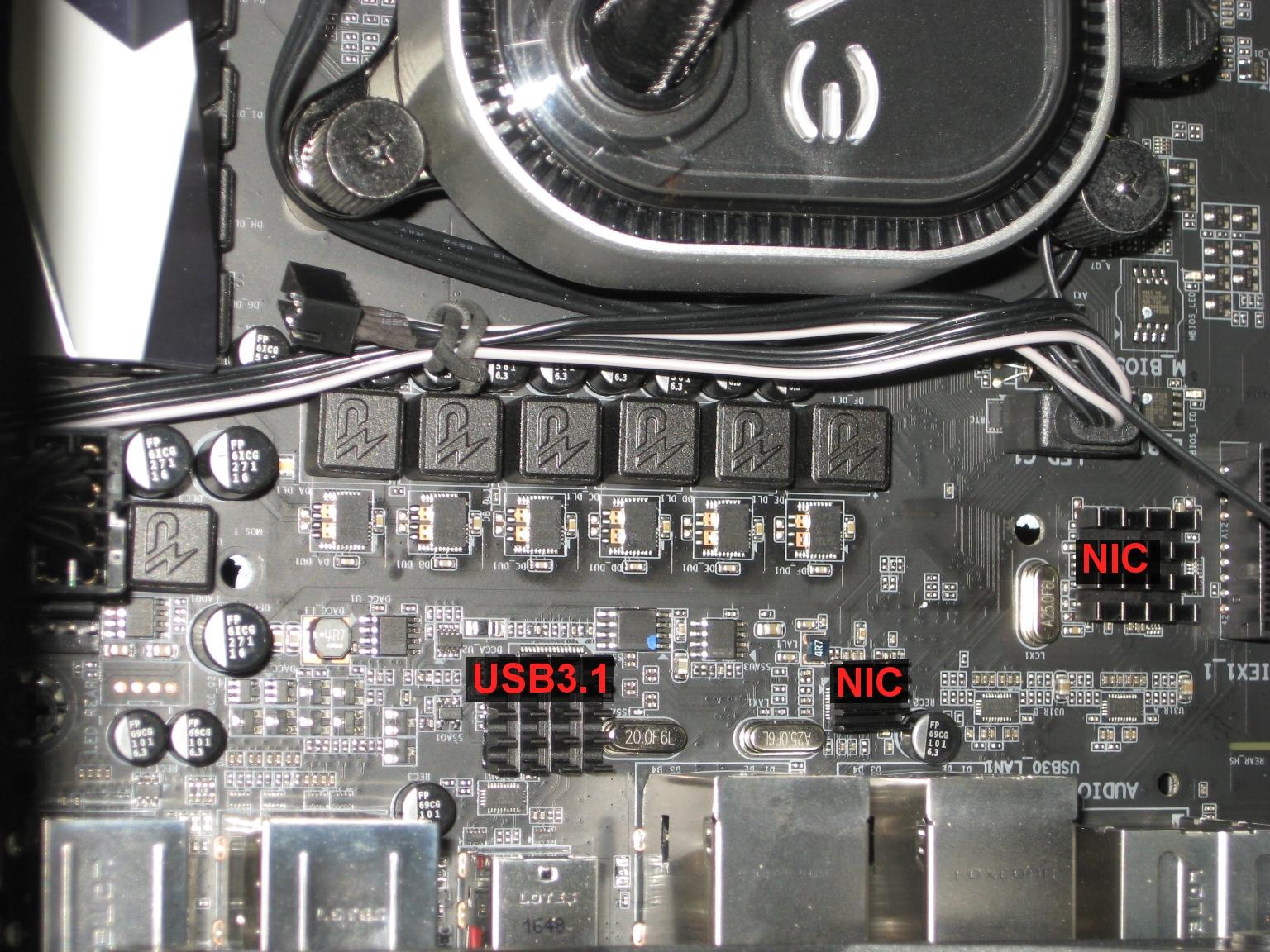
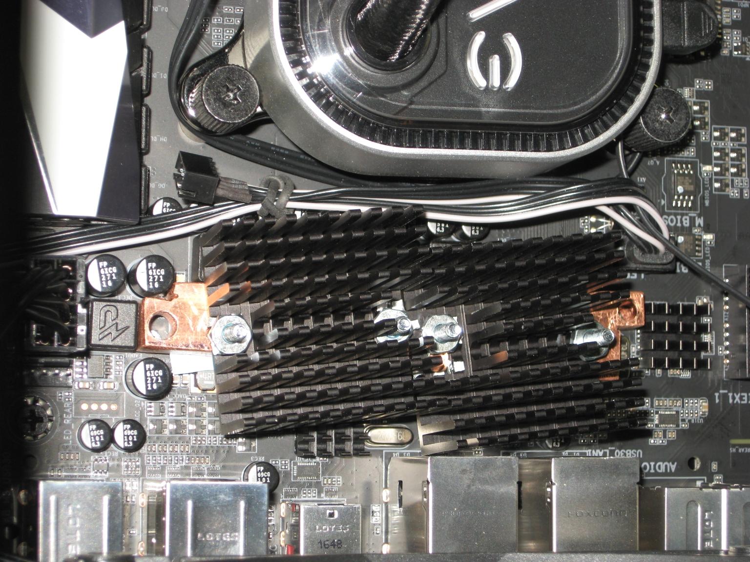
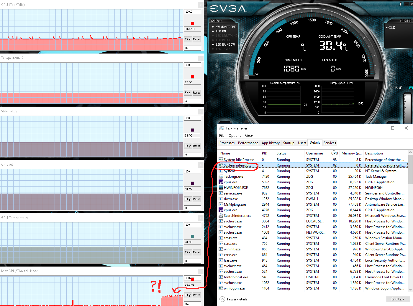
I noticed after getting the updates to work, or rather they decided to just work on there own after being stubborn for a while, that there was still a bit of a hanging process that affected the mouse and keyboard.
I thought it was rather odd that all the devices that were giving me grief were all in the same location, so I decided to do what I usually do for two of them and look further into the third. the Intel nic on the right and the 'killer' nic in the middle are devices that inherently get hot anyway, the nature of driving long cables through a transformer.
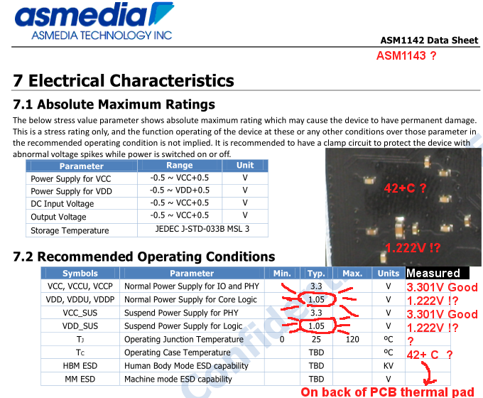
There a bit out of the way and preheated by the VRM anyway, so the heat-sinks won't hurt anything. So that out of the way, a closer look at the ASM1143 USB3.1 controller chip reviled that it was running a bit warmer than anything else back there, something I had initially thought was the 'killer' nic IC in the past weeks. And it is running a bit hot on voltage, tho still within spec, especially after adding that heat-sink on it.
The chip had been running around 10c hotter than the CPU VRM on the chip's thermal pad on the back of the motherboard (T-junction is going to be hotter than that), I now have it running under 40c, so that rules out that as a possibility. So I'm not sure at all what is causing the process to hang.
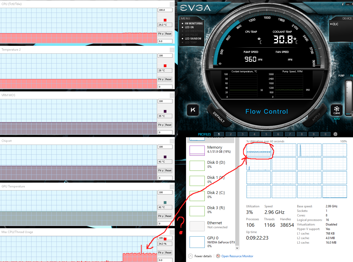
even at all stock clocks, the comp will spontaneously go into an odd lag or more like slow refresh rate, and it coincides exactly when the System Interrupts process hangs. And it hangs so hard the comp will not shut down or restart without pulling the power.
That is honestly why I have not done much on the R7 yet for 3D stuff. The only way I can describe it when the mouse goes into something akin to a 10 FPS movement rate, is imagine your trying to paint or draw something on paper with someone shaking your hand deliberately trying to keep you from doing a good job. Frustrating is an understatement. And at this point, I've tried ALL the drivers and BIOS versions for this board (I'll chat more on that angle later), it is persistent with ALL of them. There is only one thing left it can be.
If that is the case, then it will be a very long while before anything can be done about the sluggish responding interface. I can't fix windows10, and support for win7 is nonexistent for newer comps.
Have you got the latest BIOS updates for your motherboard?
That's been the main problem and main solution for 99% of Ryzen problems.
oh, my bad, I stopped at F8, as that one ran for a week without random BSOD's. F9a now in the beast, tho it may also be windows.
(edit) went for a little over 11 hours fine, then acted up. The stuck interrupt thing is not fixed by that BIOS.
Although that 40C is remarkable, I'm more impressed by the 2C you got 'for free', just by making extra slices in the original heatsink.
Yeah, that has gon to "form over function" around ten years ago, and some have gone so far as to cause more harm than good with the looks being more important than keeping the VRMs cool.
https://www.youtube.com/watch?v=0qYHWAnvXv8&t=387s
As for the temps above in the former comparison (on my x370 gigabyte gaming 5 VRM, not the GN vid), that was all with a baffle to force air through the heatsink (or the stock thermal mass, lol).
Without that baffle or a fan directly tied to the VRM blocks, the temps were much worse.
Oh, And with the 'Thermal Blanket' removed from over the VRM area, lol. It does not matter how good your heatsink is, it will not work if it's cut off from fresh air.
Like anything with electronics, it's an art to properly do thermals and making heatsinks. the fins need to go the correct way or they will block air instead of cool better.
Oh, and Buildzoid also has some good notes on VRM cooling ideas. aside from the opening statement, I forgot how bad AM4 was on lower end stuff, the methods can apply to any board. as for the need to cool the VRM on a non-gaming rig, well that applies to jus about anything current gen from AM4, to LGA1151 version 2017/18, to x299, and x399. yeah,
yeah,  that's bad for workstation class stuff of late.
https://www.youtube.com/watch?v=Ucjn6HCd2zI
I decided to open up a can of worms, to add some motor Flyback mitigation. I really have some mixed feeling about using this non-controller board, the 8-way Y-cable splitter really is not worth it for the good components, and yet I wanted to put something there.
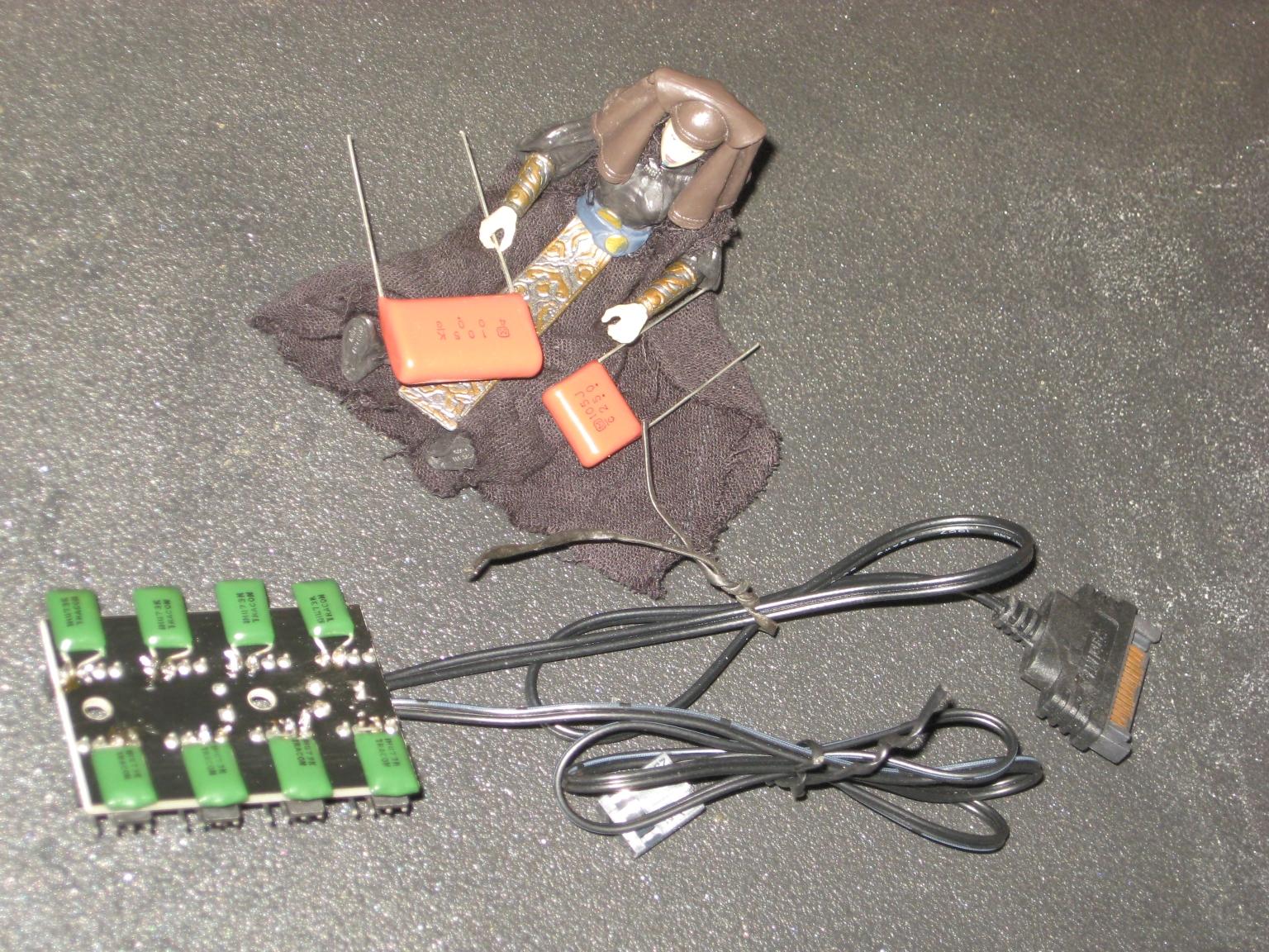
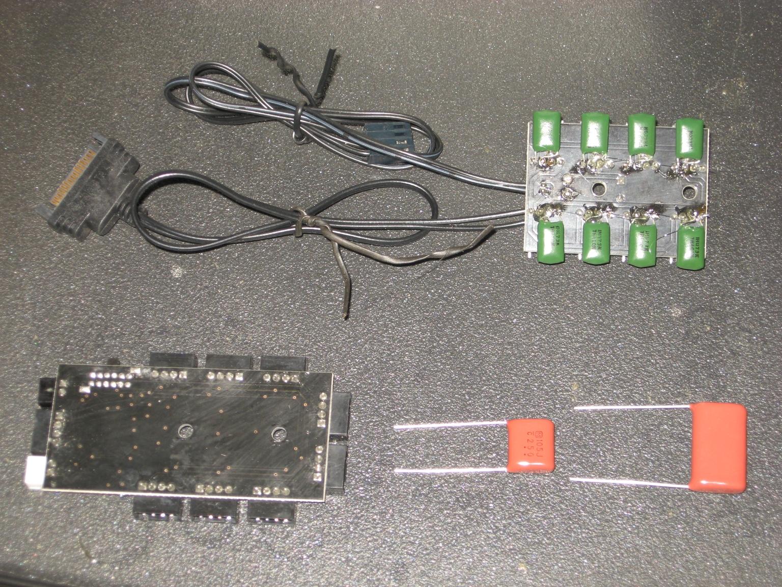
The two major problems I have with this, is only one of the fans has the 'tach' hooked up, so the other fans are running blind (Steveism forbid if one of them fails, lol), and the PWM control signal (amps) load of ALL the fans is just piled up on a single fan plug and it's controller IC on the motherboard. I will need to figure out a much better solution that at least lets 'HWiNFO64' see what All the fans are doing, and at least has a line buffer for the PWM signal to take the load off the motherboard fan plug IC (assuming I don’t deiced to ditch the software control entirely, and go with off-board dedicated logic).
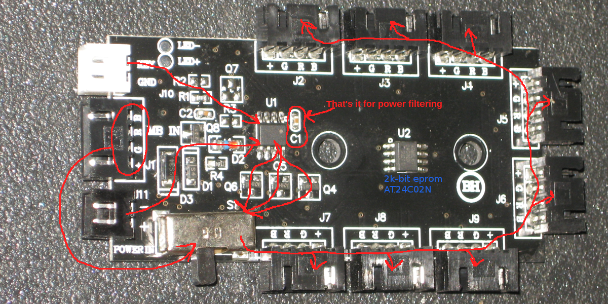
While I had the soldering iron out, and was fussing with dinner mints I decided it wouldn’t hurt If I gave the RGB (not so much of a) 'controller' some power filtering to keep the LED PWM out of the rest of the computers power lines. There really isn’t much there to begin with for power filtering, and after tracing out the power and plug traces, I have a few doubts to put it lightly (beyond the almost lack of power filtering).
It looks like all the switch does, is connect either the onboard micro-controller or the wire from the motherboard up directly to the RGB strip plugs. Now someone decided that the PIC needed an output buffer to drive the RGB output, however, the motherboard setting even bypasses that essentially turning the entire board into an 8-way splitter with no buffer at all. This really is a missed opportunity as the parts are already there for a buffer on the motherboard plug, lol.
Most small op-amps and control chips have a limited to the amount of power they can deliver to fans and LEDs. And it is not just a function of how big the output fets are in the chip, it is more a function of how much heat can be dissipated from the output section of the chip. Most control Logic chips cant handle more than 10 mA out the outputs (op-amps usually top out at 200mA), and the average LED can take up to 40 mA each, a standard RGB strip has how many LEDs, lol. And this RGB board is hooking up at least eight RGB strips to one motherboard plug (without daisy chaining strips), and that one motherboard plug probably has only one chip driving it. I really doubt that chip is happy driving that many RGB strips, and I would not be surprised if adding any more RGB strips to the case would turn that chip into a lava fountain on the desk, lol.
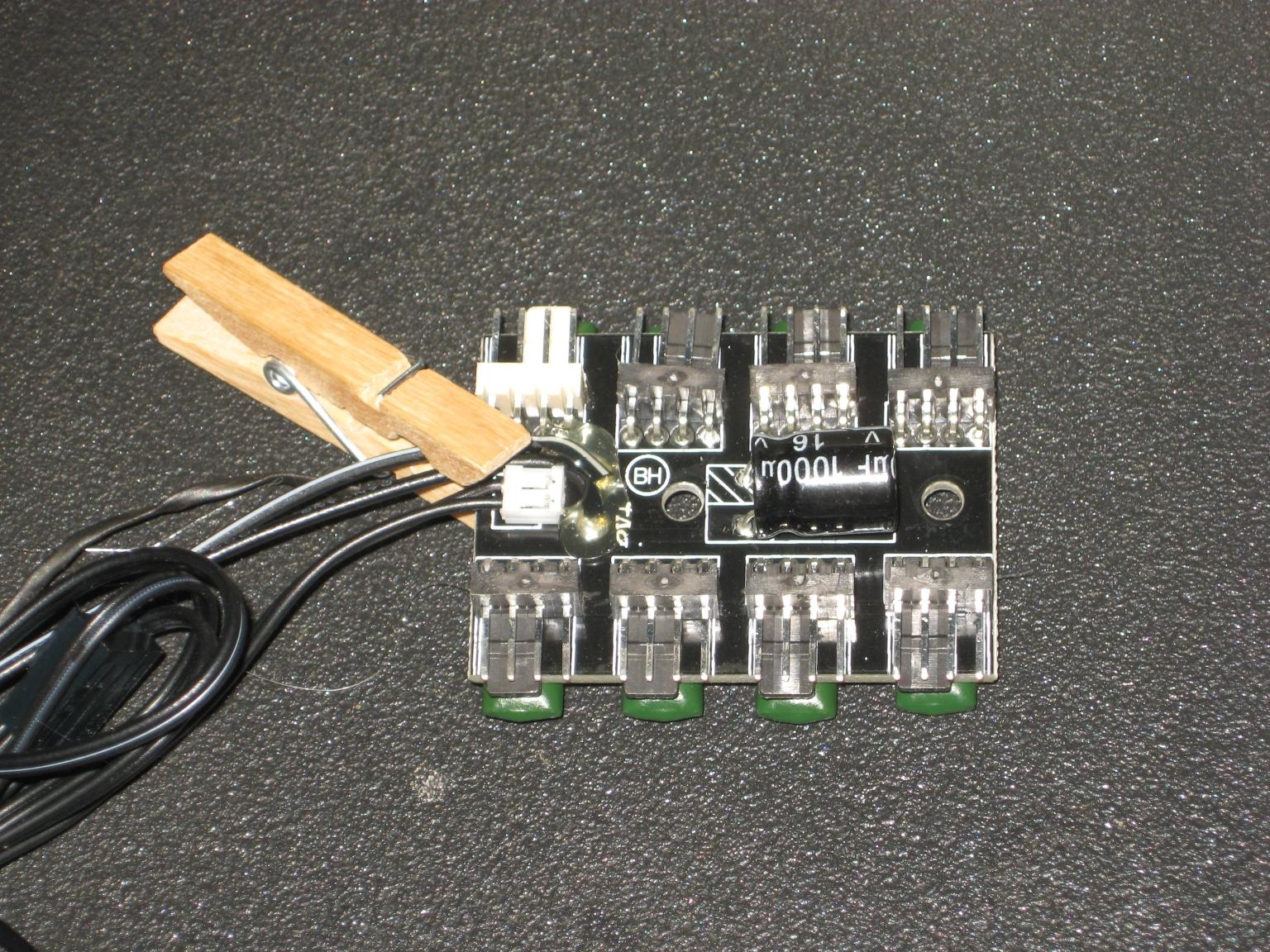
Oh, and I topped off that fan power splitter with a dab of hot-snot strain relief on them wires, because they were already starting to fray at the solder points. And power wires growing fish hooks makes me a tad nervous, as it's only a matter of time before a fish hook on a wire connects to something it's not supposed to.
As for the tach wires, well, I guess adding them isn't too much effort. I just got to find a few more dead fans to scavenge the plugs off of.
I looked outside this morning and found a pleasant surprise.
the sun is out and the deck is almost dry. So I can work on some stuff that has been bugging me for a while. Especial after watching smoke flow around the case and seeing whats going on. That front is essentially blocking most of the 140mm fans exhaust effectively reducing them to almost equivalent to a row of 120 mm fan. And that is not enough for the rad and rear exhaust fan. So I have some stuff to do that's been on the do-list for almost a month now.
I have some vents that are blocked off that I need to open up.
And I need to get the front fans opened up so they can breathe a bit better. That should open the intakes up enough to not have the graphics card sucking air in the PCI slots from the PSU exhaust.
I don't think I'll get to that top rad today, tho that is ore of a ram upgrade and fan swap testing constraint than the GPU getting fresh air from the front.
That may happen later on. The fact that three 140 mm fans cant keep up with two 120mm rad fans is a bit more pressing right now. Well, I' off to get the leaves off the deck and prep the case for some work outside, chat latter Y'all.
And these nit-picks apply to all case makers, not just SilverStone. If I didn't like the case, it would be in the trash I do have three other 26-inch tall "True Full Towers" I could just drop the guts in and be up and running if it came to that.
I'm still kicking. I did get some mods done to the computer case, testing is ongoing.
Also decided to work on my speakers at the worst posiblemoment, and had to rush that project a tad.
Then timing would get me, with a major distraction to my former plans.
Now I don't need to know much, to see that 'something' is building up in that set of graphs the past few days (and no, I don't know much more as of now). So I'm going to have some coffee and try to compose a few posts that I wanted to make almost a week or so ago (a bit more on topic here).
ok, some notes on the PM01 case as I sift through pics. Remember That funny meme about picking one fan size to not have smaller fan mounts blocking larger fans, well, I removed the blockage, lol.
And I moved the rad mount to get some memory and VRM clearance, not to say intake fan breathing room.
And I feel that I totally failed in smoothing out The Leading Edge on the cuts on the top, I'll need to try to clean that up later on.
I also discover just how impossible"Cable management" can be, Patrick and Steve are experts compared to me at that, lol.
I think I got the airflow mostly good now, tho as said, I'm still testing and heavily distracted at the same time. TMKS is getting really active of late.
ok, been buisy, and some have mentiond consern that a odd wave is a tremor or something. I'm realy sure it is only an ID or digital timestamp.
It hapens att the same time (31 to 32 minutes after the hour), and that kind of excludes natural posibilities, and the shape of the wave as well.
I have much to do, chat later on.
Aliens, using our satellites against us!
lol, yeah, that had crossed my mind. And I guess some others have used photoshop to overlay the past two weeks of that signal and it is as I had thought, the same from day to day.
I've been neglecting so much the past two weeks, and this is a rather cold morning to be doing much at all outside. I realy need to clean that
We did get some snow around the holidays, so that was nice. I hope others also are having a good holiday season.
I've been a tad distracted with volcano stuff of late, and have run into more pains of living out where cell phones don't work.
after about a week, FB decided I 'had' to verify myself with a cell phone number.
and just clicking 'continue' reverts back to that page, so FB has locked them selfs out of me using their services, just like Yahoo business. SMS does not work on landlines, and I will not pay monthly fees for a device that does not work here, lol.
Oh, and these stators for the R7 build rad, have been sitting there for over two weeks now, I think the hot glue has cured by now, lol.
(ChihYing Chen, University of California) compute nodes: Intel(R) Xeon(R) CPU E5-2670 v2 (10 core) *2, (64GB RAM, HDD: only need base system, so we chose 32GB SSD. (end quote) That's about 54 GigaFLOPS of power, with 4 nodes to produce 208 GigaFLOPS worth of weather simulation computer. That is rather impressive considering ten years ago it would take a computer the size of a gymnasium to predict where hurricanes may go, now just 4 server compute nodes, lol.
A while ago I had done some napkin math to see what it would take to get the AoA faceplant time under a minute, and that was just dumbfounding to me. Subsurface scattering isn't much more than a form of a Gaussian blur, and yet it would take more computing power than a weather simulation to do. The Ryzen is nice, it's just not that good, and clearly, the AoA subsurface code is probably the worst coded thing on this planet, lol. Boldoser was about 32 Gigaflops for the FX8350, and the R7 can be around 64 GigaFLOPS depending on OC. to quote a former post, The minimum requirement for generation 7 HD figures may as well read "You must have a minimum 320 GigaFLOPS computer that runs Windows to use HD figures in 3delight, over half a TaraFLOPS recommended".
To be honest, I haven't had that kind of time lately to be sitting here unable to use my computer, lol. And I have yet to get the R7 computer fully up and running as a render box, especially considering it is still only plugged into some junk-TN panels and money for more IPS panels will not be for a while.
* skin mats converted to Daz Default Shader on the figure.
I did get some stuff around Christmas, however, time fell short, and it sort of never happened. I'm not even sure I got the skin tone correct, because the TN panels are that bad, lol.
because I needed to convert most things to better shader before even setting up a scene, and the junk-TN and lack of time kind of made things fall behind. I haven't even had a chance to try out this d-force stuff yet, lol. I also have no idea what is up with that hat, Apparently, the Iray shader can have some incredibly compute-intensive side effects in 3delight, lol.
First impression of dForce
(edit) after about 43 minutes, it is still thinking about it, and I can't even do another screencap for TOS reasons, not to say the way the mouse doesn't move for a few seconds then spontaneously jumps to some where else when I do try to do something on the computer. Descriptively, it looked like the dress was first trying to expand and fill the entire test chamber, then it started gravitating up to the ceiling.
We have Christmas today in Russia =)
I'm telling you, the SSS code itself is the same as everywhere else in vanilla shaders. But! Shader mixer is forcing it (and all the speculars, velvets and related delight) to be run _every_time_ a ray hits. Like a shadow ray. That normally would just receive the info that the figure is fully opaque and be done.
So, every shadow ray. Every diffuse ray that does AO. How many samples do you have on your lights?.. each is a ray... per point...
That is a very good question for the maintenance crew while a d-force malfunction is being cleaned up, lol.
I recall setting the lights to the bare minimum samples to not have grainy shadows without dragging older CPUs to there knees with spot renders. That was a very long time ago before everyone went to using AoA mats on figures. Good point on the recalculating everything for each ray of anything before the rendering actually starts. If SSS forces everything to be calculated multiple times before pre-compute is done, that could explain some of the stupendous compute requirements. I remember something about a 24 (daz spotlights) and 48 (Omni AreaLight Plane), that was such a long time ago I can't even get the same daz spotlights from the menu now, lol.
Mery Christmas, by the way, Kettu (and others out that way)
I saw this sipping my morning coffee, guess where it went
Love that look on her face XD
Everything, including actual SSS. Which is a bit more than glorified gaussian. And even if it were, gaussian isn't exactly a free operation either!
Thank you!!
well, I am slightly dumbfounded. I have been replacing blocks with heatsinks for so long that I completely dismissed any possibility that a motherboard maker would actually demonstrate any hint of comprehending thermal dynamics.
I do know that many OC'ers and reviewers were beating up motherboard makers for using Oven Controlled Osculator thermal designs rather than stuff made to keep high power equipment cool.
Your eyes are not tricking you and there is nothing odd in this cup of coffee, that is an actual heatsink on that AMD X470 Gaming K7 VRM. Time will tell if, if the 8700k motherboards ever inherit anything capable of keeping the VRMs cool, it would be nice if they did. One sobering thought brought up by Chickenbeek (in the comments on GN's CES vid on the board), is that it may only be a placeholder till the final 'block' thermal mass design is worked out, it is only CES after all an things can change. If the X470 Gaming K5 ends up with a similar heatsink, a trade-in is very tempting, even considering how much effort I put into the X370 VRM heatsink I made.